|
|
The RR2D module is a new class for sliceOmatic 5.0. This class, "Rigid Registration 2D", enable you to register slices in 2D (in the plane of the slices). It can be used, for example, to re-align series if you need to move a patient between acquisitions. This is a landmark based registration technique. You need to specify landmark points on all the objects that you want to register. the registration is done in 2D only, the slices will only be transformed in their "X-Y" plane.
The registration will be applied to the children of the class. So if the class is the last before the frames, then a registration transformation will be computed for each frame. If the class is present before a Series class, then a transformation will computed for each complete series.
The first child of the RR2D class is the reference object. All the other objects will be aligned according to that one. To compute a translation, you need at least 1 marker on an object, to compute a rotation or a scale factor you need 2. All the objects are aligned in one operation using least square technique. So the reference points do not need to be present on all objects. As long as a reference point is present on any 2 objects, it will be used in the computation of the solution.
For example, if we want to align 3 objects using translations only, if we have marker #0 on objects 1, markers #0 and #1 on object 2 and marker #1 on object 3, we have enough markers on all objects to align objects 2 and 3 with 1 even though object 3 has no marker in common with object 1.
The RR2D class is enabled through the 2D Mode: "DB Class management" interface. Once you have an instance of this class in your database tree, a new "Class Registration 2D" button will be present in the Modes menu. This button will open the module's interface. |
Unaligned series
|
|
|
Aligned series |
|||


From the Graphic Interface
|
|
|
|
|
Select which of the instances of the class you want to work on. |
|
Select the current reference point. The current reference point has its button depressed. If you want to add a new reference point, first select the desired point from this list, then click on the desired position on the frames. Clicking on an existing point on the frames will make that point the current reference point.
A light on each button also indicate the reference points that exist on the current frame.
The mouse wheel can be used to change the current reference point.
|
|
|
Marker Hue |
You can change the hue of each reference point individually. The changes of hue will be applied to the current reference point.
|
|
Marker Size |
You can change the size of the reference points markers. The size changes are applied to all reference points.
|
|
Enable the back projection lines. See below for a more detailed description of this function.
|
|
|
You can select the type of transformations that the registration will apply to the frames to align them.
|
|
|
Registration Results |
Display the results of the registration for the current frame. |
|
Compute the registration for all the children of the class using a least square technique on a matrix of all the markers.
|
|
|
Save to script |
Create a file that can be used to re-create the same reference points.
|
|
All the measurement tools present on the starting frame will be copied on the target frame. This tool is also described in the "Interface tools" section of the introduction |

The Back Projection lines
|
|
The back projection lines can be very useful to detect if a marker is misplaced.
It display a line that goes from the actual position of a marker to the compute position of the marker.
If you have multiple markers, then they are all used to compute the registration of an frame. The program then use the registration information to compute where the markers from one frame would be projected on another frame. The program then display a line from that projection position to the actual marker's position. If a marker is way out of place, this will show up as a longer line. You can then use that information to decide if you have misplaced that marker and can correct its position, or maybe remove it altogether.
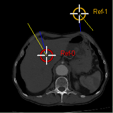
In the mode "Selected Frame", the marker of the selected frame are projected on all the other frames, and the markers of all other frames projected on the selected frame. Yellow lines connect all the computed / actual marker pairs.
In the mode "All Frames", all markers from all frames are projected on all the other frames. Yellow lines connect markers pairs from markers present on the selected frame, and blue lines connect all the other pairs. |
|
From the Display Area
The registration points are placed directly on the frames. Or if the display is in 3D, on a 3D geometry.
From the Keyboard
The following keys can also be used while the cursor is over a frame:
|
|
|
|
|
|
Key |
Action |
|
|
|
|
|
|
Del |
Delete the nearest marker. |
From the Command Line
There is no command line or variables directly associated with this class.